There is certainly more than one way of capturing a 3D image in real-time. Understanding which technique to employ in an industrial machine vision system depends though on the application in question and the particular automation problem you are trying to solve.
Each 3D machine vision technology has very different capabilities, and the 3D image quality varies significantly as a result. This makes choosing the best technology for a successful result a challenge.
In our presentations to customers, we explain that there are really only four principle techniques:
In this article we’ll provide an introduction to the basic concept of 3D imaging and discuss the advantages and disadvantages of these different techniques.
What’s important to recognize at the outset is that there can be considerable overlap between today's 3D imaging techniques. Presenting a one-to-one comparison of particular solutions is therefore hard because techniques are often combined to form a complete vision system, and sometimes there exists no clear boundary between techniques. Ultimately, it’s the quality and accuracy of 3D data int the applicable range that’s the distinguishing feature, and it simply has to meet the application requirements.
You can actually say that there are only two main approaches to real-time 3D imaging. One is ‘time-domain based’ (time-of-flight), whereas the others (stereo vision, laser triangulation, and structured light) are ‘spatial-domain based.’
Whether either approach or combination of techniques works best in an industrial automation setting depends on the specific nature of the task. How robust the solution has to be, and how practical it is to engineer within a production line environment, are additional considerations.
By producing three-dimensional data point clouds of a target object, 3D machine vision cameras are certainly free of the limitations and restrictions of more straightforward 2D solutions. However, they still need to be able to cope with the real-world influences of distance to object, obstructions, ambient light, shadows, field of view and the exact nature of the object – its size, shape and detail, flexibility, the material and its surface, whether it’s colored, reflective, transmissive, or dark and light-absorbing.

Before we go any further, let’s first consider human vision. Our eyes have two different lateral positions in our head. The distance between them, known as the ‘baseline’, is approximately 6 cm. Each eye has a slightly different view of the world, resulting in two slightly different images projected onto the retinas of our eyes.
Let's illustrate this together!
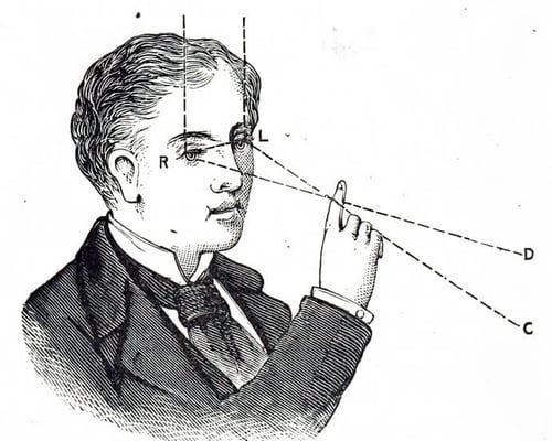
The disparity is directly dependent on the distance between the target object (your finger) and the sensor (your eyes). The human brain determines the depth of the observed scene by finding corresponding points or features in the scene for every sensing unit (cone) in each eye, turning disparities between points/features into a coherent 3D image of the scene.
In 3D machine vision, baseline then refers to the distance between two cameras, or the camera and a pattern projector. The baseline is a critical factor in 3D imaging, and increasing it affects the system in various ways:
Now, let’s consider each different spatial-domain or baseline related 3D machine vision technique.
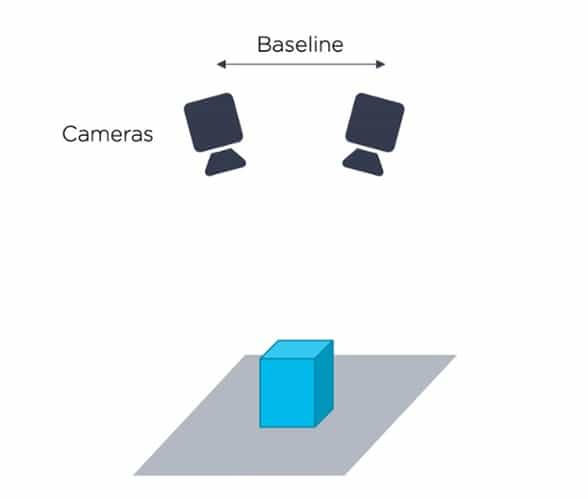
Mimicking human vision, the stereo vision technique uses a pair of cameras to record the same 2D view of the target object taken from two different angles. Knowing the fixed relative positioning of the two cameras, software compares corresponding points in the two flat images, identifies disparities and through triangulation produces a full 3D point cloud.
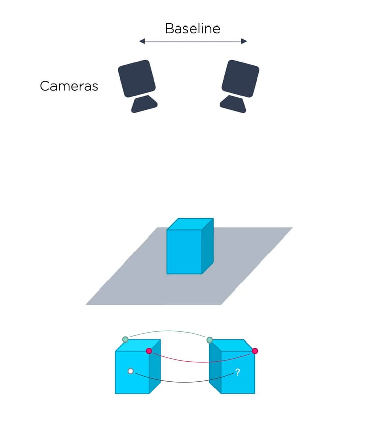
Illustration of 3D stereo vision. A challenge is establishing corresponding points.
3D imaging via stereo vision is a proven technique that offers fast image acquisition and a large field of view. It relies on ambient light and does not require special lighting or a built-in light source. Stereo vision is therefore suitable for measuring at large distances in an outdoor environment.
Unfortunately, stereo vision image quality is not comparable to that of human vision. For objects with texture, image correlation methods are typically used to establish point correspondences. This is a processor-intensive task that usually requires a long computation time. To determine correlation, the method works on a small spatial ‘neighborhood’ around each pixel, which leads to block averaging, loss of spatial resolution and accuracy.
The main difficulty with stereo vision is establishing the correspondence between points in the two or more different camera images. Feature points, such as the corners of a cube, may be identified as corresponding points, but problems arise for points that reside in the middle of a smooth, textureless surface.
Correspondence problems occur on featureless regions and can lead to a sparsely populated 3D image (i.e. fewer data points in the point cloud). Pixels with missing measurements appear ‘black’ in the point cloud.
By incorporating laser or structured light projection to add texture, the correspondence problem can be mitigated.
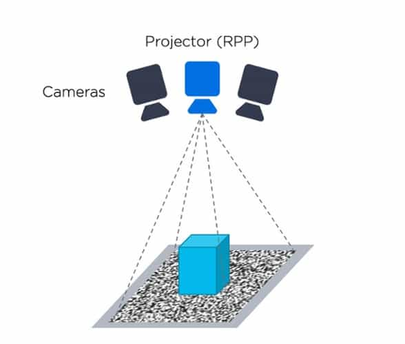
Active stereo vision is similar to stereo vision; however, it is enhanced with a random pattern projector (RPP). The RPP is often a laser with a diverging, pseudo-random pattern, which helps to establish pixel correspondence for objects with little or no texture.
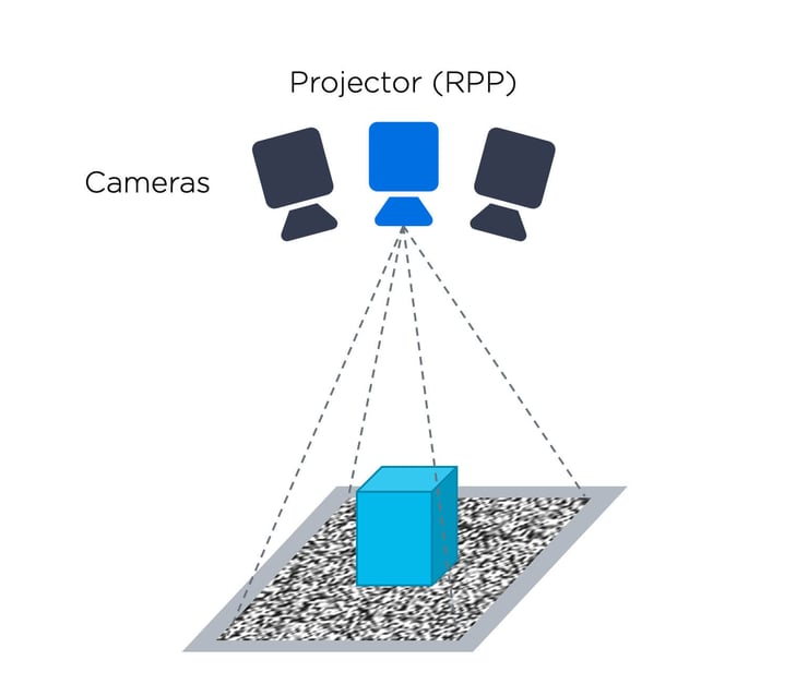
Illustration of 3D stereo vision.
The projected pattern effectively infills plain image regions with texture, mitigating the correspondence problem. However, in addition to making the whole system more complicated and costly, introducing an RPP does not reduce the existing challenges of basic stereo vision.
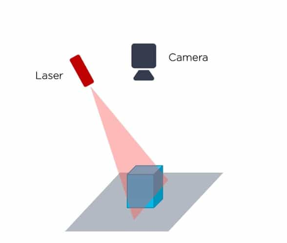
A line laser is a relatively cheap and simple active light source that can be used together with a camera to avoid the stereo vision setup with two cameras and an RPP. This old technique is simple, low cost, fast and highly accurate. Laser triangulation is one of the most popular and commonly used 3D imaging techniques and is deployed in a wide range of interior and exterior applications.
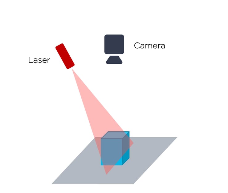
Illustration of 3D laser vision.
The laser triangulation or laser profiling technique involves moving the target object through a beam (line) of laser light. A camera arranged at a set angle to the laser emitter records an image of the laser line as it is deflected by the object’s geometric shape, thereby capturing an accurate profile of the object at a point in time.
The continuous laser scanning process repeats as the object passes through the fixed laser line. Consecutive object profiles are recorded, and a three-dimensional point cloud is generated by comparing deviations in height from the straight, non-deformed laser line.
A laser is a powerful monochromatic light source and applying a bandpass filter in front of the measuring camera can make the system very robust against ambient light. This setup does not provide color information, and laser triangulation can also struggle to acquire data from shiny and dark object surfaces.
The main disadvantage of laser triangulation is that it is relatively slow. Because it’s just a single line, it must somehow scan across the scene to create a full image. Either the entire object needs to pass through the laser line at constant velocity, or the sensor must be “swiped” across the object. A rotating or scanning mirror can steer the laser line mechanically.
The need to provide a stable means of motion control for object scanning can present engineering challenges, although given this need, laser triangulation is therefore perhaps the most suitable method for 3D imaging of objects on a moving conveyor where the conveyor can’t be stopped.
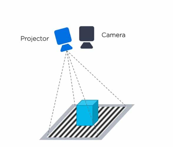
The structured light technique is similar to that of laser triangulation but is extended to a whole field. It is called a full-field method because it provides an entire 3D image of the object, and not just of a single cross-sectional line. It records the geometric distortion of a known illumination pattern projected onto the surface of a static three-dimensional target object.
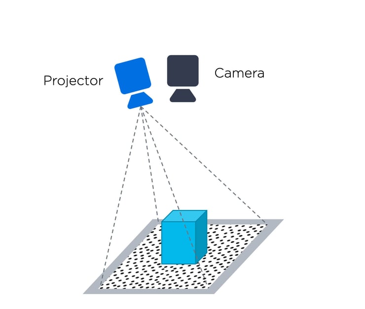
Illustration of 3D spatial vision.
A stripe (often called ‘fringe’) or grid pattern composed of a few thousand lines of high contrast light, is projected onto the target object’s complex surface. A camera captures the pattern at a set angle. Distortions from the original, flat pattern are determined, enabling a highly accurate 3D point cloud representation of the object. The structured pattern doesn’t necessarily need to be composed of lines, it can be dots or similar. Either way it must provide unique information for each region of the image.
With only one pattern, structured light is similar to active stereo (operating on a spatial region / neighborhood), but without the second camera. However, since the pattern is structured and not random, the data extraction is generally less processor intensive and the structured pattern avoids the correspondence problem. On the negative side, one pattern spatial structured light does have the same challenges as stereo vision regarding block averaging, resolution, and accuracy. Structured light systems typically also have the same problems as laser scanners concerning either specular or shiny surfaces or very dark and absorptive surfaces. These surfaces usually lead to missing data and measurement errors.
We can overcome the problem of block averaging, loss of spatial resolution and accuracy by introducing a time domain into the equation, combining spatial and time domain (as in time-coded structured light). However, lets first look at a technique which is purely time domain based.
Taking a time-domain rather than a spatial-domain approach to 3D imaging, time-of-flight laser scanners, sometimes also called LIDAR systems or laser radars, effectively remove the baseline. By measuring the time delay between emitted laser light and the reflected laser light from the object's surface, we can get a precise distance measurement.

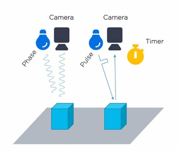
Illustration of 3D Time of Flight (TOF).
Time-of-flight (TOF) cameras represent a relatively new technology for capturing 3D range images in real-time. These cameras are very fast, capturing a whole image instead of just a point, and typically deliver intensity and range data at video frequencies or higher.
Near-infrared (NIR) light is used to illuminate the scene, and the phase of the light that reflected off the scene and back to the sensor is measured by a special sensor where each pixel contains an on-chip correlation circuit. The phase shift is proportional to the distance travelled, allowing us to measure distances from each pixel in the image to their corresponding points in the scene. Similarly, for pulse based, each pixel contains timing circuitry to find the time delay between the emitted laser pulse and the reception pulse.
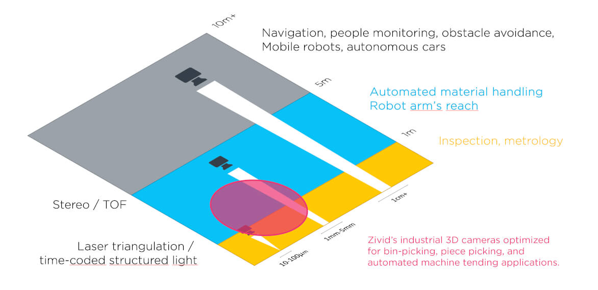
TOF cameras are complicated to manufacture, and often come with low spatial resolution, where VGA resolution is considered high-end. The complexity of design, physics of light and, by virtue of the measurement principle itself, TOF cameras have less theoretical precision than structured light systems at ranges up to 10m. Above 10m TOF systems start to become better.
One of the benefits of using time for measurement is that pixel-level processing can be performed. Imagine a region of data, where instead of it being spread out over a spatial neighborhood as previously discussed, it is now recorded at the same pixel over time. All calculations are performed at a pixel level, avoiding the analysis of spatial neighborhoods, which increases precision, and avoids block noise and loss in spatial resolution.
In a time-coded structured light 3D imaging technique, spatial domain and time domain approaches are combined. Instead of just projecting a single pattern, a series of unique patterns are projected, and the camera captures several images for the entire, coded series. Intensities observed at each pixel, at different times, are used to establish correspondences between individual pixels in the camera and the projector. Since only temporal information is used, all calculations are performed at a pixel level, avoiding the analysis of spatial neighborhoods. This removes any block noise or loss in spatial resolution.
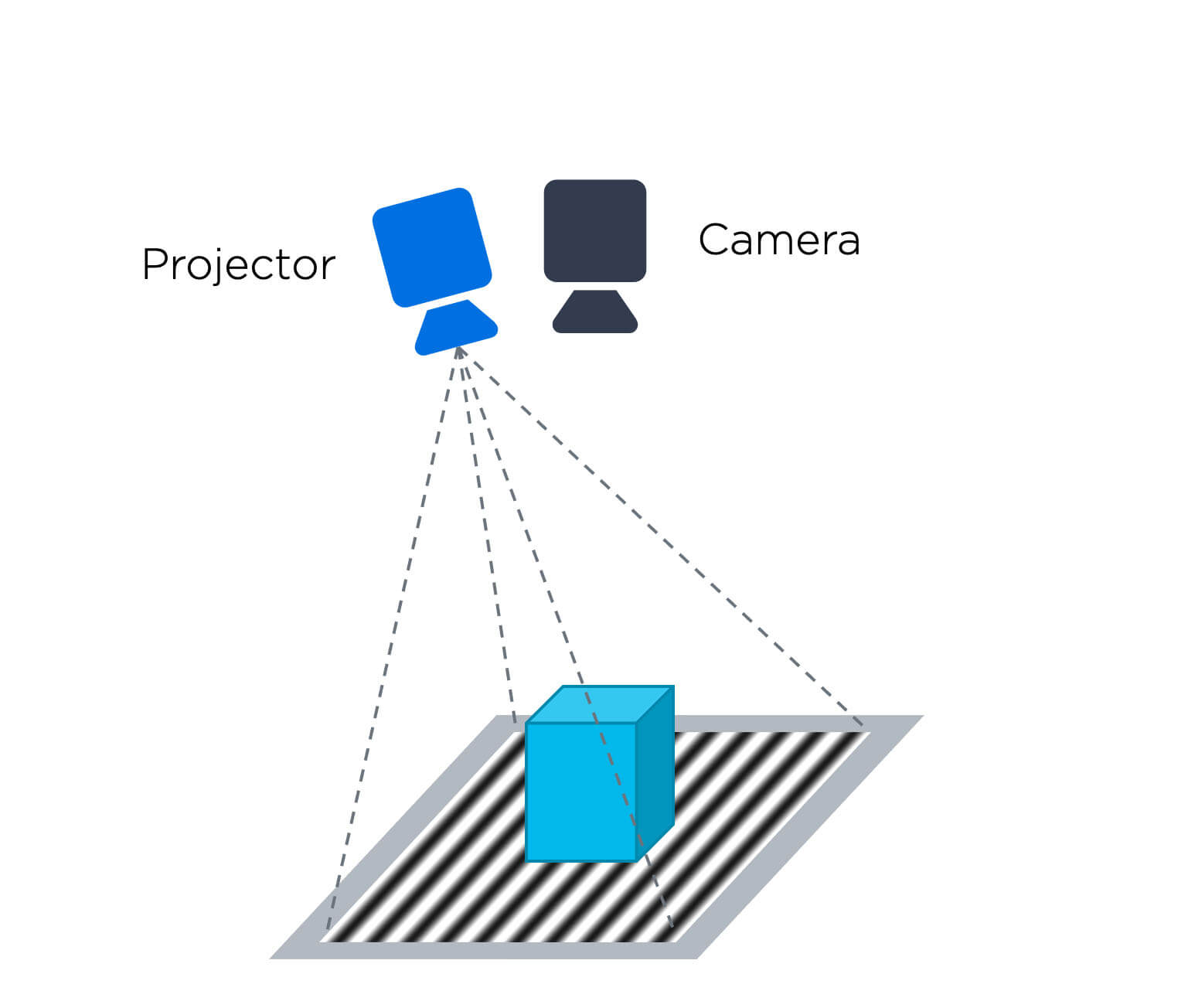
Illustration of 3D structured vision.
Achieving as much as up to 100x better precision and accuracy than other techniques, time-coded structured light is a very desirable solution for 3D machine vision. Unfortunately, capturing several images takes more time, and the target object and camera need to be static during the data acquisition. Apart from this, the pros and cons of time-coded structured light are equivalent to those of spatial structured light.
A Zivid 3D color camera is based on the same underlying technological principle as high-accuracy time-coded structured light scanners. With cutting-edge technology and innovations in both hardware and software based on several years’ research, Zivid has overcome the recognised drawbacks of the technique, whether its speed or sensitivity to specular and reflective surfaces. With a purpose-built, high-speed projector capable of projecting several hundred different smart light patterns per second, the camera is both fast and accurate, and with white light projection, handling a diversity of materials and surfaces.
We call it no-compromise 3D machine vision, and claim that if you can see more, you can do more.
Example of using time-coded structured light in bin-picking.
Capturing XYZ point cloud data and RGB color data within the same sensor chip, the camera avoids color bleeding or spatial averaging problems, and gives rise to the term 3D HDR.
Watch Svenn Arne describe how time-coded structured light can create point clouds here:
At the outset of this article we mentioned that selecting the right 3D machine vision technique is not straightforward, because it always depends on the kind of application, the type of target object and the environmental conditions. Comparing different solutions and techniques isn’t easy and unnecessary equipment ‘specmanship’ can also hinder the process.
Differentiation between solutions though is getting much clearer. To find your all-important factor in determining whether a 3D machine vision camera is fit for purpose, we’re happy to do so.